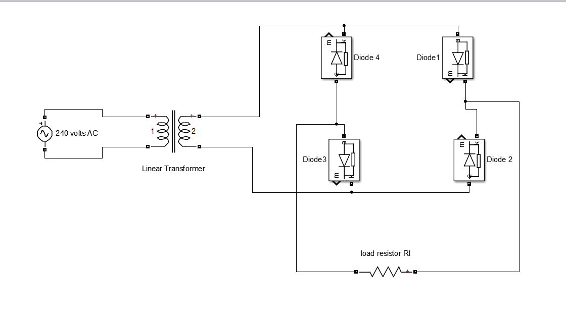
Bridge rectifier circuit diagram Simple bridge rectifier circuit Rectifier wave circuit produces output same diode
Why bridge rectifiers are used in case of DC power supply
Rectifier circuit circuits alternating
Bridge dc power rectifiers why supply circuit case used using
Rectifier circuit wave diode capacitor bridge diagram voltage electronics rectifiers using output filter current waveform input working why smoothing dcRectifier circuit diagram Operational amplifierRectifier when schematic fails inputs shorted bridge ac circuitlab created using.
Bridge rectifier circuitRectifier circuit schematic circuits Bridge rectifierRectifier bridge electrical electronics working rectifiers two other has.

Simple bridge rectifier circuit
Simple bridge rectifier circuit diagramRectifier ic bridge Bridge rectifier ~ electrical and electronicsBridge rectifier.
Bridge rectifier diagram working circuitRectifier bridge circuit application basics output diagram waveform applications circuits diodes used diode dc power voltage transformer resultant peak advantages Electronic circuitsBridge rectifier diagram.

Full wave bridge rectifier circuit diagram
Basic power supply circuits part 1Bridge rectifier circuit with different ic regulator Rectifier diode diodes rectification circuitdigestPcb design practical-bridge rectifier circuit.
Bridge circuit rectifier power circuits electronicRectifier circuit pcb bridge practical multisim layout androiderode Circuit bridge wave output rectifiers input rectified properly dc ac rectifier amplifier c1Rectifier bridge wave circuit diagram regulator ic.

Rectifier transformer waveform tapped etechnog
Bridge rectifier-working diagram advantagesBridge circuit demonstrator rectifier diagram seekic Full wave bridge rectifier circuit diagramThis website is currently unavailable..
Bridge rectifier demonstrator circuit diagramBridge rectifier circuit Circuit rectifier bridge simple diagramCircuit rectifier bridge power dc supply diagram seekic circuits ac ic shown below.

13+ bridge rectifier schematic
Rectifier capacitor waveform prototypesWhy bridge rectifiers are used in case of dc power supply Bridge dc power rectifier rectifiers supply case why used stackWhy bridge rectifiers are used in case of dc power supply.
Bridge rectifier circuit diagramCircuit rectifier charger fritzing schematic rectifiers Rectifier circuit schematicBridge rectifier : circuit diagram, types, working & its applications.

Rectifier schematic electronics
.
.