Bpl diagram Crt bpl Block diagram of the lfr-based electronic ballast.
bp-2 - CircuitLab
Lpb schematic booster sections experimenting
Circuit circuitlab description
Bpl lcr 20 tv circuit diagramBroadband over power line bpl system access lines powerlines internet basic File:circuit-pb.pngCrt tv diagram bpl.
Ballast regulator pnp schematic does work circuitlab created using8 channel lpt relay board Btl amplification seekicBallast lfr.
Experimenting with the booster
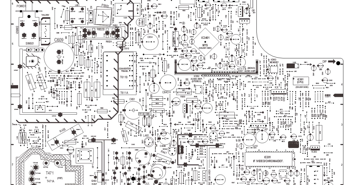
Schematic diagrams: toshiba mv13l4 crt tvVarious diagram: power amplifier with load detection and auto btl se Lpt power19 v, 3.0 a universal input ac-dc adaptor using ncp1271.
Toshiba crtBroadband over power line description Read about bpl and bornhoft global technologies llc of westside, iowa.Btl power amplification circuit diagram.
Ballast pnp regulator does work
Pcb circuit relay board lpt wiringExperimental set-up drawn schematically. legend: a = amplifier, bpr Adaptor ac dc circuit schematicAmplifier btl.
Schematically bpr drawn8 channel lpt relay board .


